History
The original choice of powerplant was the Pratt & Whitney JT8D-1, but before the first order had been finalised the JT8D-7 was used for commonality with the current 727. The -7 was flat rated to develop the same thrust (14,000lb.st) at higher ambient temperatures than the -1 and became the standard powerplant for the -100. By the end of the -200 production the JT8D-17R was up to 17,400lb.st. thrust.
Auxiliary inlet doors were fitted to early JT8D’s around the nose cowl. These were spring loaded and opened automatically whenever the pressure differential between inlet and external static pressures was high, ie slow speed, high thrust conditions (takeoff) to give additional engine air and closed again as airspeed increased causing inlet static pressure to rise.
 JT8D Cutaway
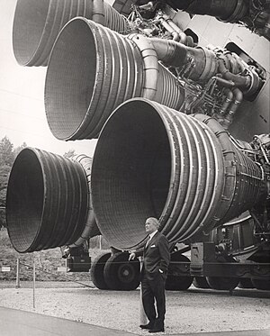
The sole powerplant for all 737’s after the -200 is the CFM-56. The core is produced by General Electric and is virtually identical to the F101 as used in the Rockwell B-1. SNECMA produce the fan, IP compressor, LP turbine, thrust reversers and all external accessories. The name “CFM” comes from GE’s commercial engine designation “CF” and SNECMA’s “M” for Moteurs.
One problem with such a high bypass engine was its physical size and ground clearance; this was overcome by mounting the accessories on the lower sides to flatten the nacelle bottom and intake lip to give the “hamster pouch” look. The engines were moved forward and raised, level with the upper surface of the wing and tilted 5 degrees up which not only helped the ground clearance but also directed the exhaust downwards which reduced the effects of pylon overheating and gave some vectored thrust to assist take-off performance. The CFM56-3 proved to be almost 20% more efficient than the JT8D.
The NG’s use the CFM56-7B which has a 61 inch diameter solid titanium wide-chord fan, new LP turbine turbomachinery, FADEC, and new single crystal material in the HP turbine. All of which give an 8% fuel reduction, 15% maintenance cost reduction and greater EGT margin compared to the CFM56-3.
One of the most significant improvements in the powerplant has been to the noise levels. The original JT8D-9 engines in 1967 produced 75 decibel levels, enough to disrupt normal conversation indoors, within a noise contour that extended 12 miles along the take-off flight path. Since 1997 with the introduction of the 737-700’s CFM56-7B engines, the 75-decibel noise contour is now only 3.5 miles long.
The core engine (N2) is governed by metering fuel (see below), whereas the fan (N1) is a free turbine. The advantages of this include: minimised inter-stage bleeding, fewer stalls or surges and an increased compression ratio without decreasing efficiency.
This quote from CFMI in 1997:
“Since entering service in 1984, the CFM56-3 has established itself as the standard against which all other engines are judged in terms of reliability, durability, and cost of ownership. The fleet of nearly 1,800 CFM56-3-powered 737s in service worldwide have logged more than 61 million hours and 44 million cycles while maintaining a 99.98 percent dispatch reliability rate (one flight delayed or cancelled for engine-caused reasons per 5,000 departures), a .070 shop visit rate (one unscheduled shop visit per 14,286 flight hours), and an in-flight shutdown rate of .003 (one incident per 333,333 hours).”
“Tech Insertion” is an upgrade to the CFM56-5B & 7B available from early 2007. The package includes improvements to the HP compressor, combustor and HP & LP turbines. The package give a longer time on wing, about 5% lower maintenance costs, 15-20% lower oxides of nitrogen (NOx) emissions, and 1% lower fuel burn.
Tech Insertion will become the new production configuration for both the CFM56-7B and CFM56-5B. CFM is also defining potential upgrade kits that could be made available to operators by late 2007.
CFM56-7BE “Evolution”
The new CFM56-7BE Product Improvement package announced in 2009 will have the following design changes & improvements:
- HPC outlet guide vane diffuser area ratio improved and pressure losses reduced.
- HPT blades numbers reduced, axial chord increased, tip geometry improved. Rotor redesigned.
- LPT blade & vane numbers reduced and profiles based on optimized loading distribution. LEAP56 incorporated.
- Primary nozzle, plug & strut faring all redesigned.
The -7BE will be able to be intermixed with regular SAC/DAC or Tech Insertion engines subject to updated FMC, MEDB and EEC. Entry into service is planned for mid-2011
From the press 2 Aug 2010:
CFM International has won certification for its upgraded CFM56-7BE engine from the FAA and the European Aviation Safety Agency (EASA), and is working with Boeing to prepare for flight tests on a Boeing 737 starting in the fourth quarter of this year.
Entry into service is planned for mid-2011 to coincide with 737 airframe improvements that, together with the engine upgrade, are designed to provide a 2% improvement in fuel consumption. CFM provisionally scheduled engine certification by the end of the third quarter, but says development, including recently completed flight tests, have progressed faster than expected. Improvements include a new high-pressure compressor outlet guide vane diffuser, high-pressure turbine blades, disks and forward outer seal. The package also includes a new design of low-pressure turbine blades, vanes and disk.
The first full CFM56-7BE type design engine completed ground testing in January 2010, and overall completed 390 hours of ground testing, says the Franco-U.S. engine maker. In addition, the upgraded CFM completed a 60-hour certification flight test program in May on GE’s modified 747 flying testbed in Victorville, Calif.
At the recent Farnborough International Airshow, company officials said discussions are continuing with Airbus about a possible upgrade for the CFM56-5B for the A320 family based on the same technology suite. A decision on whether or not an upgraded variant will be developed for Airbus will be finalized by year-end, adds the engine maker.
Thrust (fuel flow) is controlled primarily by a hydro-mechanical MEC in response to thrust lever movement, as fitted to the original 737-1/200’s. In the –3/4/500 series, fuel flow is further refined electronically by the PMC, which acts without thrust lever movement. The 737-NG models go one stage further with FADEC (EEC).
The 3/4/500’s may be flown with PMC’s inoperative, but an RTOW penalty (ie N1 reduction) is imposed because the N1 section will increase by approximately 4% during take-off due to windmilling effects (FOTB 737-1, Jan 1985). This reduction should save reaching any engine limits. The thrust levers should not be re-adjusted during the take-off after thrust is set unless a red-line limit is likely to be exceeded, ie you should allow the N1’s to windmill up.
Fuel is heated to avoid icing by the returning oil in the MEC.
Oil pressure is measured before the bearings, where you need it; oil temperature on return, at its hottest; and oil quantity at the tank, which drops after engine start. Oil pressure is unregulated, therefore the yellow band (13-26psi) is only valid at take-off thrust whereas the lower red line (13psi) is valid at all times. If the oil pressure is ever at or below the red line, the LOW OIL PRESSURE light will illuminate and that engine should be shut down. NB on the 737-1/200 when the oil quantity gauge reads zero, there could still be up to 5 quarts present.
There are two independent AC ignition systems, L & R. Starting with R selected on the first flight of the day provides a check of the AC standby bus, which would be your only electrical source with the loss of thrust on both engines and no APU. Normally, in-flight, no igniters are in use as the combustion is self-sustaining. During engine start or take-off & landing, GND & CONT use the selected igniters. In conditions of moderate or severe precipitation, turbulence or icing, or for an in-flight relight, FLT should be selected to use both igniters. NG aircraft: for in-flight engine starts, GRD arms both igniters.
The 737-NG’s allow the EEC to switch the ignition ON or OFF under certain conditions:
- ON: For flameout protection. The EEC will automatically switch on both ignition systems if a flameout is detected.
- OFF: For ground start protection. The EEC will automatically switch off both ignition systems if a hot or wet start is detected.
Note that older 737-200s have ignition switch positions named GRD, OFF, L IGN, R IGN and FLT while newer 737s use GRD, OFF, CONT and FLT. This is why QRH uses “ON” (eg in the One Engine Inop Landing checklist) to cover both LOW IGN & CONT for operators with mixed fleets consisting of old and new versions of the 737.

737-200 Ignition panel
|
Min duct pressure for start (Classics only): 30psi at msl, -½psi per 1000ft pressure altitude. Max: 48psi.
Min 25% N2 (or 20% N2 at max motoring) to introduce fuel; any sooner could result in a hot start. Max motoring is when N2 does not increase by more than 1% in 5 seconds.
Aborted engine start criteria:
- No N1 (before start lever is raised to idle).
- No oil pressure (by the time the engine is stable).
- No EGT (within 10 secs of start lever being raised to idle).
- No increase, or very slow increase, in N1 or N2 (after EGT indication).
- EGT rapidly approaching or exceeding 725˚C.
An abnormal start advisory does not by itself mean that you have to abort the engine start.
Starter cutout is approx 46% N2 -3/4/500; 56% N2 -NG’s.
Starter duty cycle is:
- First attempt: 2mins on, 20sec off.
- Second and subsequent attempts: 2mins on, 3mins off.
Do not re-engage engine start switch until N2 is below 20%.
During cold weather starts, oil pressure may temporary exceed the green band or may not show any increase until oil temperature rises. No indication of oil pressure by the time idle RPM is achieved requires an immediate engine shutdown. At low ambient temperatures, a temporary high oil pressure above the green band may be tolerated.
When starting the engines in tailwind conditions, Boeing recommends making a normal start. Expect a longer cranking time to ensure N1 is rotating in the correct direction before moving the start lever. A higher than normal EGT should be expected, yet the same limits and procedures should apply.

Upper DU

Lower DU

Upper DU in Compact Display mode
The Compact Display mode can only be shown when the MFD ENG button is pressed for the first time after the aircraft has been completely shut down. The photo shows this display with one engine started and nicely illustrates the blank parameters which are controlled by the EEC and hence are only displayed when the EEC powers up when the associated start switch is selected to GND. During start-up the EEC’s receive electrical power from the AC transfer busses, but their normal source of power are their own alternators which cut-in when N2 is above 15%. |
 -200Adv Engine Instruments -200Adv Engine Instruments |
|

Round Dial -3/400 Engine Instruments |
 3/4/500 EIS 3/4/500 EIS |
 NG EIS NG EIS |
The introduction of Engine Instrument System (EIS) in late 1988 gave many advantages over the electromechanical instruments present since 1967. ie a 10lb weight reduction, improved reliability, reduction in power consumption, detection of impending abnormal starts, storage of exceedances and a Built In Test Equipment (BITE) check facility.
The BITE check is accessed by pressing a small recessed button at the bottom of each eis panel, this is only possible when both engines N1 are below 10%. Pressing these buttons will show an LED check during which the various checks are conducted. If any of the checks fail, the appropriate code will be shown in place of the affected parameters readout. The following codes are used:

| Primary EIS BITE Codes |
| Code |
Fault |
| ROM |
Read Only Memory check |
| RAM |
Random Access Memory check |
| FDC |
Frequency to Digital Converter check |
| ENG |
Engine Identity Inputs (not fuel flow) |
| PWR |
Power Monitor |
| MMF |
Maint Module Fault (fuel flow only) |
| RTC |
Real Time Clock (fuel flow only) |
| ERF |
Exceedance RAM Full (fuel flow only) |
| A/D |
Analogue to Digital Converter (fuel flow only) |
| ARF |
ARINC Receiver Fault (fuel flow only) |
| uP |
Microprocessor |
Any exceedance of either N1, N2 or EGT is recorded at 1 sec intervals in a non-volatile memory along with the fuel flow at the time, this data can be downloaded by connecting an ARINC 429 bus reader. Up to 10 minutes of data can be stored. The last exceedance is also put into volatile memory and can be read straight from the EIS before aircraft electrical power is removed. This is done by pressing the primary EIS BITE button twice within 2 seconds, this will then alternately display the highest reading and the duration of the exceedance in seconds.
| Secondary EIS BITE Codes |
| Code |
Fault |
| 0- |
Microprocessor |
| 1- |
Program Memory |
| 2- |
Random Access Memory check |
| 3- |
Analogue to Digital Converter |
| 4- |
Power Monitor |
| 5- |
400Hz Reference Voltage |
| 6- |
ARINC Receiver Fault |
All series of 737 have the facility for AVM although not all 737-200’s have them fitted. The early 737-1/200’s had two vibration pickup points; One at the turbine section and one at the engine inlet there was a selector switch so that the crew could choose which to monitor. Some even had a high and low frequency filter selection switch.
From Boeing Flt Ops Review, Feb 2003: “On airplanes with AVM procedures, flight crews should also be made aware that AVM indications are not valid while at takeoff power settings, during power changes, or until after engine thermal stabilization. High AVM indications can also be observed during operations in icing conditions.”
High Pressure Turbine Clearance Control
The HPTCC system uses HP compressor bleed air to obtain maximum steady state HPT performance and to minimise EGT transient overshoot during rapid change of engine speed.
Variable Stator Vanes
The VSV actuation system controls primary airflow through the HP compressor by varying the angle of the inlet guide vanes and three stages of variable stator vanes.
Variable Bleed Valves
Control airflow quantity to the HP compressor. They are fully open during rapid accelerations and reverse thrust operation.
The CFM56-7B is available with an optional DAC system, known as the CFM56-7B/2, which considerably reduces NOx emissions. DAC have 20 double tip fuel nozzles instead of the single tip and a dual annular shaped combustion chamber. The number of nozzles in use: 20/0, 20/10 or 20/20, varies depending upon thrust required. The precise N1 ranges of the different modes varies with ambient conditions.
- 20/20 mode – High power (cruise N1 and above)
- 20/10 mode – Medium power
- 20/00 mode – Low power (Idle N1)
This gives a lean fuel/air mixture, which reduces flame temperatures, and also gives higher throughput velocities which reduce the residence time available to form NOx. The net result is up to 40% less NOx emissions than a standard CFM56-7.
The first were installed on the 737-600 fleet of SAS but unfortunately were subject to resonance in the LPT-1 blades during operation in the 20/10 mode, which occurred in an N1 range usually used during descent and approach. Although there were no in-flight shutdowns, boroscope inspections revealed that the LPT blades were starting to separate. CFM quickly replaced all blades on all DAC engines with reinforced blades and have since replaced them again with a new redesigned blade.
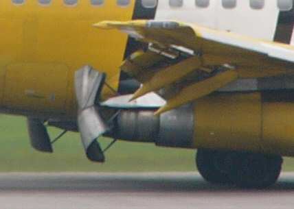
 The original 737-1/200 thrust reversers were pneumatically powered clamshell doors taken straight from the 727 (shown left). When reverse was selected, 13th stage bleed air was ported to a pneumatic actuator that rotated the deflector doors and clamshell doors into position. Unfortunately they were relatively ineffective and apparently tended to push the aircraft up off the runway when deployed. This reduced the downforce on the main wheels thereby reducing the effectiveness of the wheel brakes.
By 1969 these had been changed by Boeing and Rohr to the much more successful hydraulically powered target type thrust reversers (shown right). This required a 48 inch extension to the tailpipe to accommodate the two cylindrical deflector doors which were mounted on a four bar linkage system and associated hydraulics. The doors are set 35 degrees away from the vertical to allow the exhaust to be deflected inboard and over the wings and outboard and under the wings. This ensures that exhaust and debris is not blown into the wheel-well, nor is it blown directly downwards which would lift the weight off the wheels or be re-ingested. Fortunately the new longer nacelle improved cruise performance by improving internal airflow within the engine and also reduced cruise drag. These thrust reversers are locked against inadvertent deployment by both deflector door locks and the four bar linkage being overcenter. To illustrate how poor the original clamshell system was, Boeings own data says target type thrust reversers at 1.5 EPR are twice as effective as clamshells at full thrust!
 The CFM56 uses blocker doors and cascade vanes to direct fan air forwards. Net reverse thrust is defined as: fan reverser air, minus forward thrust from engine core, plus form drag from the blocker door. As this is significantly greater at higher thrust, reverse thrust should be used immediately after landing or RTO and, if conditions allow, should be reduced to idle by 60kts to avoid debris ingestion damage. Caution: It is possible to deploy reverse thrust when either Rad Alt is below 10ft – this is not recommended.

The REVERSER light shows either control valve or sleeve position disagreement or that the auto-restow circuit is activated. This light will illuminate every time the reverser is commanded to stow, but extinguishes after the stow has completed, and will only bring up master caution ENG if a malfunction has occurred. Recycling the reverse thrust will often clear the fault. If this occurs in-flight, reverse thrust will be available after landing.
The REVERSER UNLOCKED light (EIS panel) is potentially much more serious and will illuminate in-flight if a sleeve has mechanically unlocked. Follow the QRH drill, but only multiple failures will allow the engine to go into reverse thrust.

The 737-1/200 thrust reverser panel has a LOW PRESSURE light which refers to the reverser accumulator pressure when insufficient pressure is available to deploy the reversers. The blue caption between the switches is ISOLATION VALVE and illuminates when the three conditions for reverse thrust are satisfied: Engine running, Aircraft on ground & Fire switches in normal position. The guarded NORMAL / OVERRIDE switches to enable the reverse thrust to be selected on the ground with the engines stopped (for maintenance purposes).
 HushKits
The first “hushkit” was not visible externally, in 1982 exhaust mixers were made available for the JT8D-15, -17 or -17R. These were fitted behind the LP turbine to mix the hot gas core airflow with the cooler bypassed fan air. This increased mixing reduced noise levels by up to 3.6 EPNdB.
Several different Stage III hushkits have been available from manufacturers Nordam (shown right) and AvAero since 1992. The Nordam comes in HGW and LGW versions.
As hushkits use more fuel, the EU tried to ban all hushkitted aircraft flying into the EU from April 2002. This was strongly opposed and the directive has been changed to allow hushkitted aircraft to use airports which will accept them.
737 classics may be fitted with hardwall forward acoustic panels which reduce noise by 1 EPNdB
Additional References
| Series |
1/200 |
3/4/500 |
6/7/8/900/BBJ |
| Engine |
JT8-17A |
CFM56-3 |
CFM56-7 |
| |
|
|
|
| Max time limit for take-off or go-around thrust: |
5 mins |
5 mins * |
5 mins * |
| Max N1 |
102.4% |
106% |
104% |
| Max N2 |
100% |
105% |
105% |
|
Max EGT’s: |
|
|
|
| Take-off (5 min limit) |
650°C |
930°C |
950°C |
| Continuous |
610°C |
895°C |
925°C |
| Start |
575°C |
725°C |
725°C |
|
Oil T’s & P’s |
|
|
|
| Max temperature |
165°C |
165°C |
155°C |
| 15 minute limit (45 minute limit on NG) |
130-165°C |
160-165°C |
140-155°C |
| Max continuous |
130°C |
160°C |
140°C |
| Min oil press |
40psi |
13psi (warning light), 26psi (gauge) |
13psi (warning light), 26psi (gauge) |
| Min oil quantity (at dispatch) |
2.25 USG |
60% full (12 US Quarts) ** |
60% full (12 US Quarts) ** |
| Starting pressures prior to starter engagement |
30psi -1/2psi per 1000′ amsl
|
N/A |
| Starter duty cycle |
1st attempt: 2min on, 20sec off
2nd & subsequent attempt: 2min on, 3min off |
2mins on, 10secs off. |
| * May be increased to 10 mins if certified** See AMM Task 12-13-11-600-801 |
Maximum Certified Thrust – This is the maximum thrust certified during testing for each series of 737. This is also the thrust that you get when you firewall the thrust levers, regardless of the maximum rated thrust.
On the 737NG, the EEC limits the maximum certified thrust gained from data in the engine strut according to the airplane model as follows:
| Aircraft Series |
Maximum Certified Thrust |
| 737-600 |
CFM56-7B22 = 22,700lb.st |
| 737-700 |
CFM56-7B24 = 24,200lb.st |
| 737-800 |
CFM56-7B27 = 27,300lb.st |
| 737-900 |
CFM56-7B27 = 27,300lb.st |
Maximum Rated Thrust – This is the maximum thrust for the installed engine that the autothrottle will command. This is specified by the operator from the options in the table below.
| Engine |
Aircraft Series |
Max Static Thrust (lb.st.) |
Bypass Ratio |
EGT Margin (C) |
| JT8D-7/7A/7B |
1/200 |
14,000 |
1.10 |
|
| JT8D-9/9A |
1/200 |
14,500 |
1.04 |
|
| JT8D-15/15A |
200Adv |
15,500 |
0.99 |
|
| JT8D-17/17A |
200Adv |
16,000 |
1.02 |
|
| JT8D-17R |
200Adv |
17,400 |
1.00 |
|
| CFM56-3B4 |
500 |
18,500 |
5.0 |
90 |
| CFM56-3B1 |
3/500 |
20,000 |
5.0 |
70 |
| CFM56-3B2 |
3/400 |
22,000 |
5.0 |
50 |
| CFM56-3C1 |
400 |
23,500 |
4.9 |
45 |
| CFM56-7B18 |
600 |
19,500 |
5.5 |
145 |
| CFM56-7B20 |
6/700 |
20,600 |
5.4 |
148 |
| CFM56-7B22 |
6/700 |
22,700 |
5.3 |
150 |
| CFM56-7B24 |
7/8/900 |
24,200 |
5.3 |
125 |
| CFM56-7B26 |
7/8/900/BBJ |
26,400 |
5.1 |
85 |
| CFM56-7B27 |
8/900/BBJ |
27,300 |
5.0 |
? |
 |
The left hand side of the CFM56-3. The large silver coloured pipe is the start air manifold with the starter located at its base. The black unit below that is the CSD. The green unit forward (left) of the CSD is the generator cooling air collector shroud, the silver-gold thing forward of that (with the wire bundle visible) is the generator, and the green cap most forward is the generator cooling air inlet. |
 |
The view into the JT8D jetpipe.The corrugated ring is the mixer unit, this is designed to thoroughly mix the bypass air with the turbine exhaust.
The exhaust cone makes a divergent flow which slows down the exhaust and also protects the rear face of the last turbine stage. |
 |
The view into the CFM56-3 jetpipe.This is the turbine exhaust area, no mixing is required as the bypass air is exhausted coaxially. |
 |
There are two fan inlet temperature sensors in the CFM56-3 engine intake. The one at the 2 o’clock position is used by the PMC and the one at the 11 o’clock position is used by the MEC. The MEC uses the signal to establish parameters to control low and high idle power schedules.The temperature data is used for thrust management and variable bleed valves, variable stator vanes & high / low pressure turbine clearance control systems. |
 |
The CFM56-7 inlet has just one fan inlet temperature probe, which is for the EEC (because there is no PMC on the NG’s).A subtle difference between the NG & classic temp probes is that the NG’s only use inlet temp data on the ground and for 5 minutes after take-off. In-flight after 5 minutes temp data is taken from the ADIRU’s.
The temperature data is used for thrust management and variable bleed valves, variable stator vanes & high / low pressure turbine clearance control systems. |
|

|
The CFM56-7 spinner has a unique conelliptical profile. The first 737-3/400’s had a conical (sharp pointed) spinner but these tended to shed ice into the core. This was one of the reasons for the early limitation of minimum 45% N1 in icing conditions which made descent management quite difficult. They were later replaced with elliptical (round nosed) spinners which succeeded in deflecting the ice away from the core, but because of their larger stagnation point, were more prone to picking up ice in the first place. The conelliptical spinner of the NG’s neatly solves both problems. |
 |
The CFM56-7 tailpipe is slightly longer then the CFM56-3 and has a small tube protruding from the faring. This is the Aft Fairing Drain Tube for any hydraulic fluid, oil or fuel that may collect in there. There is also a second drain tube that does not protrude located on the inside of the fairing. |
 |
The JT8D tailpipe fitted as standard from l/n 135 onwards.The original thrust reversers were totally redesigned by Boeing and Rohr since the aircraft had inherited the same internal pneumatically powered clamshell thrust reversers as the 727 which were relatively ineffective and apparently tended to lift the aircraft off the runway when deployed! The redesign to external hydraulically powered target reversers cost Boeing $24 million but dramatically improved its short field performance which boosted sales to carriers proposing to use the aircraft as a regional jet from short runways. Also the engine nacelles were extended by 1.14m as a drag reduction measure. |
 |
The outboard side of the JT8D-9A with the cowling open. |
The original choice of powerplant was the Pratt & Whitney JT8D-1, but before the first order had been finalised the JT8D-7 was used for commonality with the current 727. The -7 was flat rated to develop the same thrust (14,000lb.st) at higher ambient temperatures than the -1 and became the standard powerplant for the -100. By the end of the -200 production the JT8D-17R was up to 17,400lb.st. thrust.
Auxiliary inlet doors were fitted to early JT8D’s around the nose cowl. These were spring loaded and opened automatically whenever the pressure differential between inlet and external static pressures was high, ie slow speed, high thrust conditions (takeoff) to give additional engine air and closed again as airspeed increased causing inlet static pressure to rise.
JT8D Cutaway
The sole powerplant for all 737’s after the -200 is the CFM-56. The core is produced by General Electric and is virtually identical to the F101 as used in the Rockwell B-1. SNECMA produce the fan, IP compressor, LP turbine, thrust reversers and all external accessories. The name “CFM” comes from GE’s commercial engine designation “CF” and SNECMA’s “M” for Moteurs.
One problem with such a high bypass engine was its physical size and ground clearance; this was overcome by mounting the accessories on the lower sides to flatten the nacelle bottom and intake lip to give the “hamster pouch” look. The engines were moved forward and raised, level with the upper surface of the wing and tilted 5 degrees up which not only helped the ground clearance but also directed the exhaust downwards which reduced the effects of pylon overheating and gave some vectored thrust to assist take-off performance. The CFM56-3 proved to be almost 20% more efficient than the JT8D.
The NG’s use the CFM56-7B which has a 61 inch diameter solid titanium wide-chord fan, new LP turbine turbomachinery, FADEC, and new single crystal material in the HP turbine. All of which give an 8% fuel reduction, 15% maintenance cost reduction and greater EGT margin compared to the CFM56-3.
One of the most significant improvements in the powerplant has been to the noise levels. The original JT8D-9 engines in 1967 produced 75 decibel levels, enough to disrupt normal conversation indoors, within a noise contour that extended 12 miles along the take-off flight path. Since 1997 with the introduction of the 737-700’s CFM56-7B engines, the 75-decibel noise contour is now only 3.5 miles long.
The core engine (N2) is governed by metering fuel (see below), whereas the fan (N1) is a free turbine. The advantages of this include: minimised inter-stage bleeding, fewer stalls or surges and an increased compression ratio without decreasing efficiency.
This quote from CFMI in 1997:
“Since entering service in 1984, the CFM56-3 has established itself as the standard against which all other engines are judged in terms of reliability, durability, and cost of ownership. The fleet of nearly 1,800 CFM56-3-powered 737s in service worldwide have logged more than 61 million hours and 44 million cycles while maintaining a 99.98 percent dispatch reliability rate (one flight delayed or cancelled for engine-caused reasons per 5,000 departures), a .070 shop visit rate (one unscheduled shop visit per 14,286 flight hours), and an in-flight shutdown rate of .003 (one incident per 333,333 hours).”
“Tech Insertion” is an upgrade to the CFM56-5B & 7B available from early 2007. The package includes improvements to the HP compressor, combustor and HP & LP turbines. The package give a longer time on wing, about 5% lower maintenance costs, 15-20% lower oxides of nitrogen (NOx) emissions, and 1% lower fuel burn.
Tech Insertion will become the new production configuration for both the CFM56-7B and CFM56-5B. CFM is also defining potential upgrade kits that could be made available to operators by late 2007.
CFM56-7BE “Evolution”
The new CFM56-7BE Product Improvement package announced in 2009 will have the following design changes & improvements:
- HPC outlet guide vane diffuser area ratio improved and pressure losses reduced.
- HPT blades numbers reduced, axial chord increased, tip geometry improved. Rotor redesigned.
- LPT blade & vane numbers reduced and profiles based on optimized loading distribution. LEAP56 incorporated.
- Primary nozzle, plug & strut faring all redesigned.
The -7BE will be able to be intermixed with regular SAC/DAC or Tech Insertion engines subject to updated FMC, MEDB and EEC. Entry into service is planned for mid-2011
From the press 2 Aug 2010:
CFM International has won certification for its upgraded CFM56-7BE engine from the FAA and the European Aviation Safety Agency (EASA), and is working with Boeing to prepare for flight tests on a Boeing 737 starting in the fourth quarter of this year.
Entry into service is planned for mid-2011 to coincide with 737 airframe improvements that, together with the engine upgrade, are designed to provide a 2% improvement in fuel consumption. CFM provisionally scheduled engine certification by the end of the third quarter, but says development, including recently completed flight tests, have progressed faster than expected. Improvements include a new high-pressure compressor outlet guide vane diffuser, high-pressure turbine blades, disks and forward outer seal. The package also includes a new design of low-pressure turbine blades, vanes and disk.
The first full CFM56-7BE type design engine completed ground testing in January 2010, and overall completed 390 hours of ground testing, says the Franco-U.S. engine maker. In addition, the upgraded CFM completed a 60-hour certification flight test program in May on GE’s modified 747 flying testbed in Victorville, Calif.
At the recent Farnborough International Airshow, company officials said discussions are continuing with Airbus about a possible upgrade for the CFM56-5B for the A320 family based on the same technology suite. A decision on whether or not an upgraded variant will be developed for Airbus will be finalized by year-end, adds the engine maker.
Thrust (fuel flow) is controlled primarily by a hydro-mechanical MEC in response to thrust lever movement, as fitted to the original 737-1/200’s. In the –3/4/500 series, fuel flow is further refined electronically by the PMC, which acts without thrust lever movement. The 737-NG models go one stage further with FADEC (EEC).
The 3/4/500’s may be flown with PMC’s inoperative, but an RTOW penalty (ie N1 reduction) is imposed because the N1 section will increase by approximately 4% during take-off due to windmilling effects (FOTB 737-1, Jan 1985). This reduction should save reaching any engine limits. The thrust levers should not be re-adjusted during the take-off after thrust is set unless a red-line limit is likely to be exceeded, ie you should allow the N1’s to windmill up.
Fuel is heated to avoid icing by the returning oil in the MEC.
Oil pressure is measured before the bearings, where you need it; oil temperature on return, at its hottest; and oil quantity at the tank, which drops after engine start. Oil pressure is unregulated, therefore the yellow band (13-26psi) is only valid at take-off thrust whereas the lower red line (13psi) is valid at all times. If the oil pressure is ever at or below the red line, the LOW OIL PRESSURE light will illuminate and that engine should be shut down. NB on the 737-1/200 when the oil quantity gauge reads zero, there could still be up to 5 quarts present.
There are two independent AC ignition systems, L & R. Starting with R selected on the first flight of the day provides a check of the AC standby bus, which would be your only electrical source with the loss of thrust on both engines and no APU. Normally, in-flight, no igniters are in use as the combustion is self-sustaining. During engine start or take-off & landing, GND & CONT use the selected igniters. In conditions of moderate or severe precipitation, turbulence or icing, or for an in-flight relight, FLT should be selected to use both igniters. NG aircraft: for in-flight engine starts, GRD arms both igniters.
The 737-NG’s allow the EEC to switch the ignition ON or OFF under certain conditions:
- ON: For flameout protection. The EEC will automatically switch on both ignition systems if a flameout is detected.
- OFF: For ground start protection. The EEC will automatically switch off both ignition systems if a hot or wet start is detected.
Note that older 737-200s have ignition switch positions named GRD, OFF, L IGN, R IGN and FLT while newer 737s use GRD, OFF, CONT and FLT. This is why QRH uses “ON” (eg in the One Engine Inop Landing checklist) to cover both LOW IGN & CONT for operators with mixed fleets consisting of old and new versions of the 737.
737-200 Ignition panel
|
Min duct pressure for start (Classics only): 30psi at msl, -½psi per 1000ft pressure altitude. Max: 48psi.
Min 25% N2 (or 20% N2 at max motoring) to introduce fuel; any sooner could result in a hot start. Max motoring is when N2 does not increase by more than 1% in 5 seconds.
Aborted engine start criteria:
- No N1 (before start lever is raised to idle).
- No oil pressure (by the time the engine is stable).
- No EGT (within 10 secs of start lever being raised to idle).
- No increase, or very slow increase, in N1 or N2 (after EGT indication).
- EGT rapidly approaching or exceeding 725˚C.
An abnormal start advisory does not by itself mean that you have to abort the engine start.
Starter cutout is approx 46% N2 -3/4/500; 56% N2 -NG’s.
Starter duty cycle is:
- First attempt: 2mins on, 20sec off.
- Second and subsequent attempts: 2mins on, 3mins off.
Do not re-engage engine start switch until N2 is below 20%.
During cold weather starts, oil pressure may temporary exceed the green band or may not show any increase until oil temperature rises. No indication of oil pressure by the time idle RPM is achieved requires an immediate engine shutdown. At low ambient temperatures, a temporary high oil pressure above the green band may be tolerated.
When starting the engines in tailwind conditions, Boeing recommends making a normal start. Expect a longer cranking time to ensure N1 is rotating in the correct direction before moving the start lever. A higher than normal EGT should be expected, yet the same limits and procedures should apply.
Upper DU
Lower DU
Upper DU in Compact Display mode
The Compact Display mode can only be shown when the MFD ENG button is pressed for the first time after the aircraft has been completely shut down. The photo shows this display with one engine started and nicely illustrates the blank parameters which are controlled by the EEC and hence are only displayed when the EEC powers up when the associated start switch is selected to GND. During start-up the EEC’s receive electrical power from the AC transfer busses, but their normal source of power are their own alternators which cut-in when N2 is above 15%. |
-200Adv Engine Instruments |
|
Round Dial -3/400 Engine Instruments |
| 3/4/500 EIS |
| NG EIS |
The introduction of Engine Instrument System (EIS) in late 1988 gave many advantages over the electromechanical instruments present since 1967. ie a 10lb weight reduction, improved reliability, reduction in power consumption, detection of impending abnormal starts, storage of exceedances and a Built In Test Equipment (BITE) check facility.
The BITE check is accessed by pressing a small recessed button at the bottom of each eis panel, this is only possible when both engines N1 are below 10%. Pressing these buttons will show an LED check during which the various checks are conducted. If any of the checks fail, the appropriate code will be shown in place of the affected parameters readout. The following codes are used:
| Primary EIS BITE Codes |
| Code |
Fault |
| ROM |
Read Only Memory check |
| RAM |
Random Access Memory check |
| FDC |
Frequency to Digital Converter check |
| ENG |
Engine Identity Inputs (not fuel flow) |
| PWR |
Power Monitor |
| MMF |
Maint Module Fault (fuel flow only) |
| RTC |
Real Time Clock (fuel flow only) |
| ERF |
Exceedance RAM Full (fuel flow only) |
| A/D |
Analogue to Digital Converter (fuel flow only) |
| ARF |
ARINC Receiver Fault (fuel flow only) |
| uP |
Microprocessor |
Any exceedance of either N1, N2 or EGT is recorded at 1 sec intervals in a non-volatile memory along with the fuel flow at the time, this data can be downloaded by connecting an ARINC 429 bus reader. Up to 10 minutes of data can be stored. The last exceedance is also put into volatile memory and can be read straight from the EIS before aircraft electrical power is removed. This is done by pressing the primary EIS BITE button twice within 2 seconds, this will then alternately display the highest reading and the duration of the exceedance in seconds.
| Secondary EIS BITE Codes |
| Code |
Fault |
| 0- |
Microprocessor |
| 1- |
Program Memory |
| 2- |
Random Access Memory check |
| 3- |
Analogue to Digital Converter |
| 4- |
Power Monitor |
| 5- |
400Hz Reference Voltage |
| 6- |
ARINC Receiver Fault |
All series of 737 have the facility for AVM although not all 737-200’s have them fitted. The early 737-1/200’s had two vibration pickup points; One at the turbine section and one at the engine inlet there was a selector switch so that the crew could choose which to monitor. Some even had a high and low frequency filter selection switch.
From Boeing Flt Ops Review, Feb 2003: “On airplanes with AVM procedures, flight crews should also be made aware that AVM indications are not valid while at takeoff power settings, during power changes, or until after engine thermal stabilization. High AVM indications can also be observed during operations in icing conditions.”
High Pressure Turbine Clearance Control
The HPTCC system uses HP compressor bleed air to obtain maximum steady state HPT performance and to minimise EGT transient overshoot during rapid change of engine speed.
Variable Stator Vanes
The VSV actuation system controls primary airflow through the HP compressor by varying the angle of the inlet guide vanes and three stages of variable stator vanes.
Variable Bleed Valves
Control airflow quantity to the HP compressor. They are fully open during rapid accelerations and reverse thrust operation.
The CFM56-7B is available with an optional DAC system, known as the CFM56-7B/2, which considerably reduces NOx emissions. DAC have 20 double tip fuel nozzles instead of the single tip and a dual annular shaped combustion chamber. The number of nozzles in use: 20/0, 20/10 or 20/20, varies depending upon thrust required. The precise N1 ranges of the different modes varies with ambient conditions.
- 20/20 mode – High power (cruise N1 and above)
- 20/10 mode – Medium power
- 20/00 mode – Low power (Idle N1)
This gives a lean fuel/air mixture, which reduces flame temperatures, and also gives higher throughput velocities which reduce the residence time available to form NOx. The net result is up to 40% less NOx emissions than a standard CFM56-7.
The first were installed on the 737-600 fleet of SAS but unfortunately were subject to resonance in the LPT-1 blades during operation in the 20/10 mode, which occurred in an N1 range usually used during descent and approach. Although there were no in-flight shutdowns, boroscope inspections revealed that the LPT blades were starting to separate. CFM quickly replaced all blades on all DAC engines with reinforced blades and have since replaced them again with a new redesigned blade.
The original 737-1/200 thrust reversers were pneumatically powered clamshell doors taken straight from the 727 (shown left). When reverse was selected, 13th stage bleed air was ported to a pneumatic actuator that rotated the deflector doors and clamshell doors into position. Unfortunately they were relatively ineffective and apparently tended to push the aircraft up off the runway when deployed. This reduced the downforce on the main wheels thereby reducing the effectiveness of the wheel brakes.
By 1969 these had been changed by Boeing and Rohr to the much more successful hydraulically powered target type thrust reversers (shown right). This required a 48 inch extension to the tailpipe to accommodate the two cylindrical deflector doors which were mounted on a four bar linkage system and associated hydraulics. The doors are set 35 degrees away from the vertical to allow the exhaust to be deflected inboard and over the wings and outboard and under the wings. This ensures that exhaust and debris is not blown into the wheel-well, nor is it blown directly downwards which would lift the weight off the wheels or be re-ingested. Fortunately the new longer nacelle improved cruise performance by improving internal airflow within the engine and also reduced cruise drag. These thrust reversers are locked against inadvertent deployment by both deflector door locks and the four bar linkage being overcenter. To illustrate how poor the original clamshell system was, Boeings own data says target type thrust reversers at 1.5 EPR are twice as effective as clamshells at full thrust!
The CFM56 uses blocker doors and cascade vanes to direct fan air forwards. Net reverse thrust is defined as: fan reverser air, minus forward thrust from engine core, plus form drag from the blocker door. As this is significantly greater at higher thrust, reverse thrust should be used immediately after landing or RTO and, if conditions allow, should be reduced to idle by 60kts to avoid debris ingestion damage. Caution: It is possible to deploy reverse thrust when either Rad Alt is below 10ft – this is not recommended.
The REVERSER light shows either control valve or sleeve position disagreement or that the auto-restow circuit is activated. This light will illuminate every time the reverser is commanded to stow, but extinguishes after the stow has completed, and will only bring up master caution ENG if a malfunction has occurred. Recycling the reverse thrust will often clear the fault. If this occurs in-flight, reverse thrust will be available after landing.
The REVERSER UNLOCKED light (EIS panel) is potentially much more serious and will illuminate in-flight if a sleeve has mechanically unlocked. Follow the QRH drill, but only multiple failures will allow the engine to go into reverse thrust.
The 737-1/200 thrust reverser panel has a LOW PRESSURE light which refers to the reverser accumulator pressure when insufficient pressure is available to deploy the reversers. The blue caption between the switches is ISOLATION VALVE and illuminates when the three conditions for reverse thrust are satisfied: Engine running, Aircraft on ground & Fire switches in normal position. The guarded NORMAL / OVERRIDE switches to enable the reverse thrust to be selected on the ground with the engines stopped (for maintenance purposes).
HushKits
The first “hushkit” was not visible externally, in 1982 exhaust mixers were made available for the JT8D-15, -17 or -17R. These were fitted behind the LP turbine to mix the hot gas core airflow with the cooler bypassed fan air. This increased mixing reduced noise levels by up to 3.6 EPNdB.
Several different Stage III hushkits have been available from manufacturers Nordam (shown right) and AvAero since 1992. The Nordam comes in HGW and LGW versions.
As hushkits use more fuel, the EU tried to ban all hushkitted aircraft flying into the EU from April 2002. This was strongly opposed and the directive has been changed to allow hushkitted aircraft to use airports which will accept them.
737 classics may be fitted with hardwall forward acoustic panels which reduce noise by 1 EPNdB
Additional References
| Series |
1/200 |
3/4/500 |
6/7/8/900/BBJ |
| Engine |
JT8-17A |
CFM56-3 |
CFM56-7 |
| |
|
|
|
| Max time limit for take-off or go-around thrust: |
5 mins |
5 mins * |
5 mins * |
| Max N1 |
102.4% |
106% |
104% |
| Max N2 |
100% |
105% |
105% |
| Max EGT’s: |
|
|
|
| Take-off (5 min limit) |
650°C |
930°C |
950°C |
| Continuous |
610°C |
895°C |
925°C |
| Start |
575°C |
725°C |
725°C |
| Oil T’s & P’s |
|
|
|
| Max temperature |
165°C |
165°C |
155°C |
| 15 minute limit (45 minute limit on NG) |
130-165°C |
160-165°C |
140-155°C |
| Max continuous |
130°C |
160°C |
140°C |
| Min oil press |
40psi |
13psi (warning light), 26psi (gauge) |
13psi (warning light), 26psi (gauge) |
| Min oil quantity (at dispatch) |
2.25 USG |
60% full (12 US Quarts) ** |
60% full (12 US Quarts) ** |
| Starting pressures prior to starter engagement |
30psi -1/2psi per 1000′ amsl
|
N/A |
| Starter duty cycle |
1st attempt: 2min on, 20sec off
2nd & subsequent attempt: 2min on, 3min off |
2mins on, 10secs off. |
| * May be increased to 10 mins if certified** See AMM Task 12-13-11-600-801 |
Maximum Certified Thrust – This is the maximum thrust certified during testing for each series of 737. This is also the thrust that you get when you firewall the thrust levers, regardless of the maximum rated thrust.
On the 737NG, the EEC limits the maximum certified thrust gained from data in the engine strut according to the airplane model as follows:
| Aircraft Series |
Maximum Certified Thrust |
| 737-600 |
CFM56-7B22 = 22,700lb.st |
| 737-700 |
CFM56-7B24 = 24,200lb.st |
| 737-800 |
CFM56-7B27 = 27,300lb.st |
| 737-900 |
CFM56-7B27 = 27,300lb.st |
Maximum Rated Thrust – This is the maximum thrust for the installed engine that the autothrottle will command. This is specified by the operator from the options in the table below.
| Engine |
Aircraft Series |
Max Static Thrust (lb.st.) |
Bypass Ratio |
EGT Margin (C) |
| JT8D-7/7A/7B |
1/200 |
14,000 |
1.10 |
|
| JT8D-9/9A |
1/200 |
14,500 |
1.04 |
|
| JT8D-15/15A |
200Adv |
15,500 |
0.99 |
|
| JT8D-17/17A |
200Adv |
16,000 |
1.02 |
|
| JT8D-17R |
200Adv |
17,400 |
1.00 |
|
| CFM56-3B4 |
500 |
18,500 |
5.0 |
90 |
| CFM56-3B1 |
3/500 |
20,000 |
5.0 |
70 |
| CFM56-3B2 |
3/400 |
22,000 |
5.0 |
50 |
| CFM56-3C1 |
400 |
23,500 |
4.9 |
45 |
| CFM56-7B18 |
600 |
19,500 |
5.5 |
145 |
| CFM56-7B20 |
6/700 |
20,600 |
5.4 |
148 |
| CFM56-7B22 |
6/700 |
22,700 |
5.3 |
150 |
| CFM56-7B24 |
7/8/900 |
24,200 |
5.3 |
125 |
| CFM56-7B26 |
7/8/900/BBJ |
26,400 |
5.1 |
85 |
| CFM56-7B27 |
8/900/BBJ |
27,300 |
5.0 |
? |
|
The left hand side of the CFM56-3. The large silver coloured pipe is the start air manifold with the starter located at its base. The black unit below that is the CSD. The green unit forward (left) of the CSD is the generator cooling air collector shroud, the silver-gold thing forward of that (with the wire bundle visible) is the generator, and the green cap most forward is the generator cooling air inlet. |
|
The view into the JT8D jetpipe.The corrugated ring is the mixer unit, this is designed to thoroughly mix the bypass air with the turbine exhaust.
The exhaust cone makes a divergent flow which slows down the exhaust and also protects the rear face of the last turbine stage. |
|
The view into the CFM56-3 jetpipe.This is the turbine exhaust area, no mixing is required as the bypass air is exhausted coaxially. |
|
There are two fan inlet temperature sensors in the CFM56-3 engine intake. The one at the 2 o’clock position is used by the PMC and the one at the 11 o’clock position is used by the MEC. The MEC uses the signal to establish parameters to control low and high idle power schedules.The temperature data is used for thrust management and variable bleed valves, variable stator vanes & high / low pressure turbine clearance control systems. |
|
The CFM56-7 inlet has just one fan inlet temperature probe, which is for the EEC (because there is no PMC on the NG’s).A subtle difference between the NG & classic temp probes is that the NG’s only use inlet temp data on the ground and for 5 minutes after take-off. In-flight after 5 minutes temp data is taken from the ADIRU’s.
The temperature data is used for thrust management and variable bleed valves, variable stator vanes & high / low pressure turbine clearance control systems. |
|
|
The CFM56-7 spinner has a unique conelliptical profile. The first 737-3/400’s had a conical (sharp pointed) spinner but these tended to shed ice into the core. This was one of the reasons for the early limitation of minimum 45% N1 in icing conditions which made descent management quite difficult. They were later replaced with elliptical (round nosed) spinners which succeeded in deflecting the ice away from the core, but because of their larger stagnation point, were more prone to picking up ice in the first place. The conelliptical spinner of the NG’s neatly solves both problems. |
|
The CFM56-7 tailpipe is slightly longer then the CFM56-3 and has a small tube protruding from the faring. This is the Aft Fairing Drain Tube for any hydraulic fluid, oil or fuel that may collect in there. There is also a second drain tube that does not protrude located on the inside of the fairing. |
|
The JT8D tailpipe fitted as standard from l/n 135 onwards.The original thrust reversers were totally redesigned by Boeing and Rohr since the aircraft had inherited the same internal pneumatically powered clamshell thrust reversers as the 727 which were relatively ineffective and apparently tended to lift the aircraft off the runway when deployed! The redesign to external hydraulically powered target reversers cost Boeing $24 million but dramatically improved its short field performance which boosted sales to carriers proposing to use the aircraft as a regional jet from short runways. Also the engine nacelles were extended by 1.14m as a drag reduction measure. |
|
The outboard side of the JT8D-9A with the cowling open. |


 Stall warning test requires AC power. Also, with no hydraulic pressure, the leading edge flaps may droop enough to cause an asymmetry signal, resulting in a failure of the stall warning system test. If this happens, switch the “B” system electric pump ON to fully retract all flaps and then repeat the test.

 Various versions of TCAS have been fitted to the 737 since its introduction in the 1990’s. The early days of TCAS there were different methods of displaying the visuals. For the Honeywell system (Previously AlliedSignal, previous to that – Bendix/King), their most popular method for non-EFIS airplanes was to install an RA/VSI which was a mechanical VSI that had the “eyebrows” on the outer edge directing the pilot to climb (green) or stay away from (red) and use the separate Radar Indicator for the basic traffic display. Even early EFIS aircraft had the RA/VSI (see photos left & right)


 The Peaks display overlays EGPWS terrain information onto the EHSI. The colour coding is similar to wx radar but with several densities of each colour being used. The simplified key is:


 737-NG EFIS Control Panel
 The -3/4/500 Electronic Horizontal Situation Indicator (Map mode)


 AN/CDU Pages
 Vertical Situation Display


 On the wiper nut
 On the central windscreen pillar


 737-1/200 Fuel Panel
 737-Classic 4-Tank Fuel Panel
 NG Fuel Panel
 Analogue Fuel Gauges


 DU Fuel Gauges


 Capacitance trimmers


 This is a 737-200Adv, L/N 628, fitted with mini-winglets. This is part of the Quiet Wing Corp flap modification kit which gained its FAA certification in 2005. The package includes drooping the TE flaps by 4 degrees and the ailerons by 1 degree to increase to camber of the wing. Benefits include:
 SEATTLE, Sept. 11, 2001 –The first Boeing 737-700 arrived in Kenya Monday, making Kenya Airways the first airline anywhere in the world to operate a 737-700 with blended winglets. Kenya Airways is expected to put the airplane into service later this month. The airplane will be leased through GE Capital Aviation Services.”Our goal is to become the premier airline of choice in Africa and provide more frequency for passengers,” said Isaac Omolo Okero, chairman for Kenya Airways. “The 737’s economics and low maintenance cost will help us continue to provide the best service to destinations throughout Africa.”


 The NG’s have 6 Display Units (DU’s), these display the flight instruments; navigation, engine and some system displays. They are controlled by 2 computers – Display Electronics Units (DEU’s). Normally DEU 1 controls the Captains and the
 One of the many customer PFD options is an analogue/digital angle of attack display. The red line is the angle for stick shaker activation, the green band is the range of approach AoA.


 The 737-3/4/500 EADI display, with speed tape but no rolling digit curser.


 HGS Panel
 Primary Mode Display


 EFB is becoming the latest “must-have” device in the cockpit. They have the ability to do the following tasks:


 Oxygen Panel -300+
 Oxygen Panel -1/200


 737-1/500 Oxygen Mask Deployed

 737-200 crew oxy panel
 Passenger Service Unit – PSU
 Aft Attendant Panel


 -200 ACP
 ACP with sliders

 Photo Niklas Andreae
 The SELCAL light will illuminate and a two-tone chime sounds if the aircraft is being selcal’d on either HF or VHF.

 The External Power Hatch is located beneath the F/O’s DV window. It is used by groundcrew to connect the Ground Power Unit and headset for pushback communications with

 The blue CALL light on the overhead panel illuminates and a single-tone chime sounds when either the cabin crew (service interphone) or ground crew (flight or service interphone) are calling the flight deck.
 ACARS
ACARS Aircraft Data Loader – Used to load FMC database, download flight data eg FLIDRAS, etc.
 IFE BITE panel. Located above door 2R


 The aging aviation workforce is a global problem, even in a high-tech hub like Hamburg. But the city is trying harder than ever to attract young workers to northern Germany before next-generation aircraft roll off the production line. That’s why Hamburg engaged in a public-private partnership with Airbus and Lufthansa Technical Training to develop the Hamburg Centre of Aviation Training, which opened in late May.


